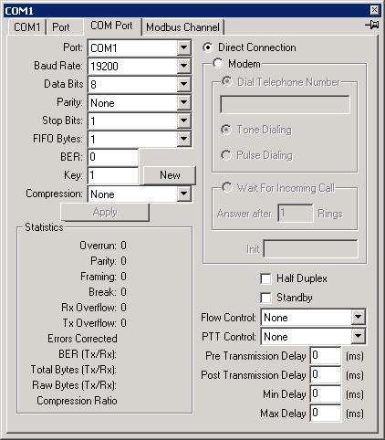
| Port |
Name of COM Port. |
|---|
| Baud Rate |
Transmission rate in bits per second. |
|---|
| Data Bits |
Number of data bits per byte. |
|---|
| Parity |
Choose None, Odd, Even, Mark or Space parity. |
|---|
| Stop Bits |
1, 1.5 or 2 stop bits. |
|---|
| FIFO Bytes |
If you system have an 16550 UART that has a 16 byte receive buffer, then the FIFO setting should match the system Receive Buffer size (for Windows 95, start/settings/control panel/system/Device Manager/Port/Communication Ports/COMx/Port Settings/Advanced). A value of 8 seems adequate for most situations. A lower value will give better response time, but will use more CPU time. It is for end of receive frame detection. The system will assume that the end of frame is reached if does not receive any more data after that amount of character time. |
|---|
| BER |
The encoding Bit Error Ratio. Set to 0 to disable Reed Solomon Forward Error Correction (with Pseudo-random symbol interleaving). The software will dynamically use RS(15,k) to RS(2047,k) depending on the BER and frame size. The second number is the measured BER of the transmitted data, the BER should be greater than this value. Each end must use the same BER. |
|---|
| Key |
32 number for pseudo-random symbol interleaving. Press New to generate a new number. Each end must use the same key. |
|---|
| Compression |
ZIP software data compression.
| None |
Do not use compression |
|---|
| Frame |
Compress at frame level only. |
|---|
| Streaming |
Streaming compression. Compression information are maintained across frame, this achieve much higher level of compression. The compression information are only reset on timeout. |
|---|
|
|---|
| Statistics |
Communication Statistics
| Overrun |
Number of character overrun errors |
|---|
| Parity |
Number of parity errors |
|---|
| Framing |
Number of framing errors |
|---|
| Break |
Number of breaks |
|---|
| Rx Overflow |
Number of times the system receive buffer overflowed |
|---|
| Tx Overflow |
Number of times the system transmit buffer overflowed |
|---|
| Errors Corrected(Tx/Rx) |
Number of errors corrected on transmitted and received data. |
|---|
| BER(Tx/Rx) |
Bit Error Ratio of transmitted and received data. |
|---|
| Compression(Tx/Rx) |
Compression ratio of Transmit and Receive data |
|---|
| Bytes Total(Tx/Rx) |
Total number of bytes transmitted and received |
|---|
|
|---|
| Flow Control |
Input and Output flow control
| None |
No flow control |
|---|
| XON/XOFF |
Software Xon/Xoff flow control. |
|---|
| RTS/CTS |
Raise RTS when input buffer is less than one-half full. Lower RTS when input buffer is more than three quarters full. Transmit only when CTS is high. |
|---|
| DTR/DSR |
Raise DTR when input buffer is less than one-half full. Lower DTR when input buffer is more than three quarters full. Transmit only when DSR is high. |
|---|
| DCD collision avoidance |
For use in half duplex, multi-dropped system. Continuously wait for DCD to be low for at least the random quiescent time before each transmission. The quiescent time is a random time between min and max delay. |
|---|
| CTS collision avoidance |
For use in half duplex, multi-dropped system. Continuously wait for CTS to be low for at least the random quiescent time before each transmission. The quiescent time is a random time between min and max delay. |
|---|
| CTS |
Transmit only when CTS is high. |
|---|
| DSR |
Transmit only when DSR is high. |
|---|
|
|---|
| Direct Connection |
Direct connection to device. |
|---|
| Modem |
Use Modem. |
|---|
| Dial Telephone Number |
Telephone number to dial to make a connection. |
|---|
| Tone Dialling |
Use Tone dialling. |
|---|
| Pulse Dialling |
Use Pulse dialling. |
|---|
| Wait for incoming call |
Wait for incoming call. |
|---|
| Answer after n rings |
Answer incoming call after n rings |
|---|
| Init Sequence |
Modem initialisation sequence. Turn on Carrier Detect Signal when remote carrier signal is present, hang up when DTR is low and use Word responses. |
|---|
| Half Duplex |
For use in situations where the Transmit and Receive lines are tied together. When enabled, the echoed transmitted characters are discarded. |
|---|
| Standby |
Not used |
|---|
| PTT Control |
Press To Talk Control.
| None |
RTS and DTR are on all the time |
|---|
| RTS |
Raise RTS only when sending data |
|---|
| DTR |
Raise DTR only when sending data |
|---|
| RTS and DTR |
Raise RTS and DTR only when sending data |
|---|
|
|---|
| Pre Transmission Delay (On Delay) |
Used with PTT Control, raise RTS or DTR and wait this time before transmitting data. |
|---|
| Post Transmission Delay (Off Delay) |
Used with PTT Control, after all data are transmitted, wait this time before dropping RTS or DTR. |
|---|
| Min Delay |
Used with DCD or CTS collision avoidance. |
|---|
| Max Delay |
Used with DCD or CTS collision avoidance. |
|---|